- 您现在的位置:买卖IC网 > Sheet目录528 > TRF3702IRHCG4 (Texas Instruments)IC QUADRATURE MODULATOR 16-VQFN
�� ����
����
����TRF3702�
�www.ti.com�
�SLWS149A� –� SEPTEMBER� 2004� –� REVISED� AUGUST� 2006�
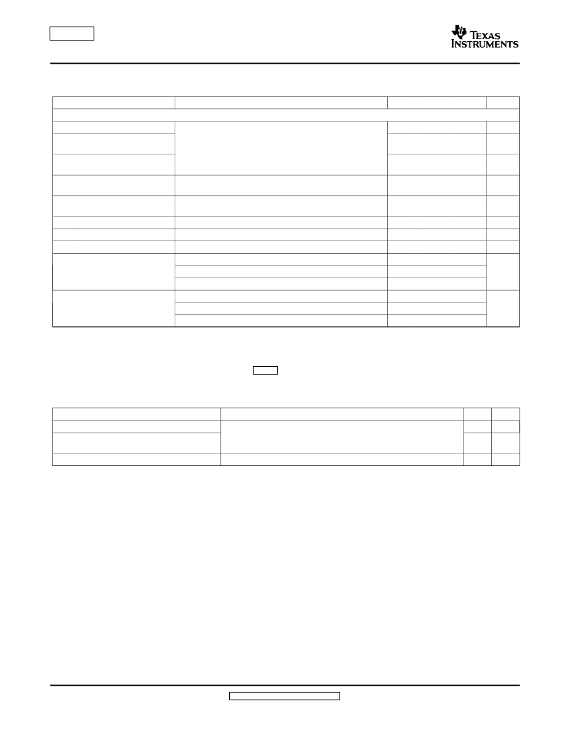
�RF� OUTPUT� PERFORMANCE�
�Over� recommended� operating� conditions,� VCC� =� 5� V,� VCM� =� 3.7� V,� f� LO� =� 2.1� GHz� at� 0� dBm� (unless� otherwise� specified)�
�PARAMETER�
�TEST� CONDITIONS�
�MIN�
�TYP�
�MAX�
�UNIT�
�Single� and� Two-Tone� Specifications�
�Output� power�
�–5�
�–3�
�dBm�
�Second� baseband� harmonic�
�(USB� or� LSB)� (2)�
�Third� baseband� harmonic�
�(USB� or� LSB)� (2)�
�IMD� 3�
�P1dB� (output� compression�
�point)�
�I,� Q� (1)� =� 1� Vp-p,� f� BB� =� 928� kHz�
�I,� Q� (1)� =� 1� Vp-p,� fBB� =� 928� kHz� (two-tone� signal,�
�f� BB1� =� 928� kHz,� f� BB2� =� 992� kHz)�
�–50�
�–60�
�–55�
�7�
�–42�
�–51�
�–47�
�dBc�
�dBc�
�dBc�
�dBm�
�NSD�
�Noise� spectral� density�
�WCDMA� ACPR�
�impedance� (4)�
�RFOUT� pin�
�60-MHz� offset� from� carrier,� P� out� =� 0� dBm,� over� temperature�
�Single� carrier,� channel� power� =� –14� dBm�
�–151�
�71�
�35� +� j27�
�–148.5� (3)� dBm/Hz�
�dBc�
�?�
�I,� Q� (1)� =� 1� Vp-p,� f� BB� =� 928� kHz,� unadjusted�
�30�
�Carrier� suppression�
�Sideband� suppression�
�I,� Q� (1)� =� 1� Vp-p,� f� BB� =� 928� kHz,� optimized�
�I,� Q� (1)� =� 1� Vp-p,� f� BB� =� 928� kHz,� over� temperature� (5)�
�I,� Q� (1)� =� 1� Vp-p,� f� BB� =� 928� kHz,� unadjusted�
�I,� Q� (1)� =� 1� Vp-p,� f� BB� =� 928� kHz,� optimized�
�I,� Q� (1)� =� 1� Vp-p,� f� BB� =� 928� kHz,� over� temperature� (5)�
�55�
�47�
�37�
�55�
�47�
�dBc�
�dBc�
�(1)�
�(2)�
�(3)�
�(4)�
�(5)�
�I� ,� Q� =� 1� Vp-p� implies� that� the� magnitude� of� the� signal� at� each� input� pin� IVIN,� IREF,� QVIN,� QREF� is� equal� to� 500� mVp-p.�
�USB� =� upper� sideband.� LSB� =� lower� sideband.�
�Maximum� noise� values� are� assured� by� statistical� characterization� only,� not� production� testing.� The� values� specified� are� over� the� entire�
�temperature� range,� T� A� =� –40� °� C� to� 85� °� C.�
�For� a� listing� of� impedances� at� various� frequencies,� see� Table� 1� .�
�After� optimization� at� room� temperature.� See� the� Definitions� of� Selected� Specifications� section.�
�THERMAL� CHARACTERISTICS�
�PARAMETER�
�CONDITION�
�NOM�
�UNIT�
�R� θ� JA�
�R� θ� JM�
�R� θ� JC�
�Thermal� resistace,� junction� to� ambient�
�Thermal� resistace,� junction� to� mounting�
�surface�
�Thermal� resistace,� junction� to� case�
�Soldered� pad� using� four-layer� JEDEC� board� with� four� thermal� vias�
�Soldered� pad� using� two-layer� JEDEC� board� with� four� thermal� vias�
�42.8�
�24.8�
�67.6�
�°� C/W�
�°� C/W�
�°� C/W�
�DEFINITIONS� OF� SELECTED� SPECIFICATIONS�
�Unadjusted� Carrier� Suppression�
�This� specification� measures� the� amount� by� which� the� local� oscillator� component� is� attenuated� in� the� output�
�spectrum� of� the� modulator� relative� to� the� carrier.� It� is� assumed� that� the� baseband� inputs� delivered� to� the� pins� of�
�the� TRF3702� are� perfectly� matched� to� have� the� same� dc� offset� (VCM).� This� includes� all� four� baseband� inputs:�
�IVIN,� QVIN,� IREF� and� QREF.� Unadjusted� carrier� suppression� is� measured� in� dBc.�
�Adjusted� (Optimized)� Carrier� Suppression�
�This� differs� from� the� unadjusted� suppression� number� in� that� the� dc� offsets� of� the� baseband� inputs� are� iteratively�
�adjusted� around� their� theoretical� value� of� VCM� to� yield� the� maximum� suppression� of� the� LO� component� in� the�
�output� spectrum.� Adjusted� carrier� suppression� is� measured� in� dBc.�
�6�
�Submit� Documentation� Feedback�
�发布紧急采购,3分钟左右您将得到回复。
相关PDF资料
TRF3705IRGET
IC QUADRATURE MODULATOR 24VQFN
TRF7970AEVM
EVAL MODULE FOR TRF7970A
TRM-418-LT
TRANSCEIVER RF 418MHZ LT SERIES
TRM-900-NT
RF TXRX 915MHZ NT SERIES
TRX08GVP2540
TXRX OPT SCFF 8.5GB/S 850NM
TS-320240BRNO
TCH PANEL 140X104 RESISTIVE MONO
TS-TFT3.5Z
TOUCH PANEL 140X1.4.0 TFT
TS3-75B3
SENSOR THERMAL MOXIE NTC 75C
相关代理商/技术参数
TRF3702IRHCR
功能描述:调节器/解调器 1.5GHz-2.5GHz Quad Mod RoHS:否 制造商:Texas Instruments 封装 / 箱体:PVQFN-N24 封装:Reel
TRF3702IRHCRG4
功能描述:调节器/解调器 1.5GHz-2.5GHz Quad Mod RoHS:否 制造商:Texas Instruments 封装 / 箱体:PVQFN-N24 封装:Reel
TRF3703
制造商:TI 制造商全称:Texas Instruments 功能描述:0.4-GHz TO 4-GHz QUADRATURE MODULATOR
TRF3703_07
制造商:TI 制造商全称:Texas Instruments 功能描述:0.4-GHz TO 4-GHz QUADRATURE MODULATOR
TRF3703_08
制造商:TI 制造商全称:Texas Instruments 功能描述:0.4-GHz TO 4-GHz QUADRATURE MODULATOR
TRF370315
制造商:TI 制造商全称:Texas Instruments 功能描述:0.35-GHz TO 4-GHz QUADRATURE MODULATORS
TRF3703-15EVM
功能描述:射频开发工具 QUADRATURE MOD RoHS:否 制造商:Taiyo Yuden 产品:Wireless Modules 类型:Wireless Audio 工具用于评估:WYSAAVDX7 频率: 工作电源电压:3.4 V to 5.5 V
TRF370315IRGER
功能描述:调节器/解调器 0.4-4.0GHz IQ Mod
RoHS:否 制造商:Texas Instruments 封装 / 箱体:PVQFN-N24 封装:Reel